|
|
|
|
|
|
|
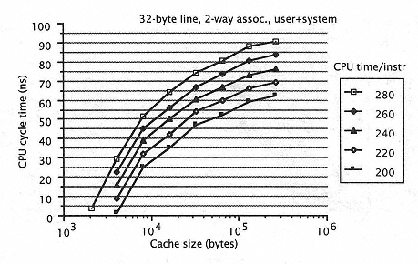
Figure 5.42
CPU time per instruction as a function of CPU cycle time and cache size. |
|
|
|
|
|
|
|
|
We now consider CPU cycle time vs. cache size. |
|
|
|
|
|
|
|
|
Suppose our initial choice is set at 50ns cycle time and 16KB cache. Figure 5.42 shows the design space around the initial choice. From this figure, CTPI is 240 ns at the chosen point. This means a 4.17 MIPS machine. |
|
|
|
|
|
|
|
|
When resource constraints are also considered, we may want to select a new design point: |
|
|
|
|
|
|
|
|
If we are running out of resources, we need to free up resources by sacrificing speed. For example, we may reduce the cache size from 16KB to 8KB, or, alternatively, increase the CPU cycle time from 50 ns to 65 ns. In either case, the machine slows down from 4.17 MIPS to about 3.6 MIPS (CTPI of 280ns) as we move to a higher contour in Figure 5.42. |
|
|
|
|
|
|
|
|
If we have extra resources, we may want to speed up the machine. The 200ns CTPI contour in Figure 5.42 gives choices that lead to a 5 MIPS machine. We may increase the cache size from 16KB to 64KB, or decrease the cycle time from 50ns to 35ns (although the latter case may not always be possible). |
|
|
|
|
|
|
|
|
In general, the gradient of the contour lines in Figure 5.42 gives the most effective direction to change machine speed. As cache size increases, the slope of the contours decreases from more than 20 ns per doubling of cache size to less than 5 ns per doubling of cache size. This suggests that for small caches, it is more effective to improve performance by doubling the cache size than by reducing CPU cycle time (if that is feasible). For large caches, the opposite is preferred. |
|
|
|
|
|
|
|
|
In cases when CPU cycle time is determined by cache, the choice of cache size becomes less obvious. In this case, any increase in cache size may also increase CPU cycle time. There is a tradeoff between smaller miss ratio |
|
|
|
|
|